M2Slim Install Guide
Step 4: Soldering
Overview
While the soldering for this mod is not recommended for beginners the design of the flex PCB pads and cutouts have been optimised to make soldering as easy as possible.The biggest concern when soldering will be avoiding overheating the flex PCB as it is made of plastic. For this reason a temperature controlled iron is required, preferably of the cartridge type (such as Hakko T12 or JBC C245).
Temperature
As a general rule I try to keep contact with the flex PCB at 1-2 seconds at a time regardless of temperature to avoid overheating. This should not be an issue if you are using flux.The manufacturer does not recommending going above 260C but this is likely for longer durations in a reflow oven. I have tested going up to 320C using leaded solder without damage but staying around 230C-240C is easy with flux and leaded solder. Lead free solder requires at least +30C higher temperatures which may make thermal management harder.Feel free to increase the iron temperature to 300-340C when soldering to the ground plane of the PS2 to compensate for the large thermal mass. Struggling with a low temp is ironically more likely to cause damage than a short burst of higher temperature.Since the PS2 likely uses unleaded solder mixing in lead may cause issues over time. However lead free solder will require higher temperatures. The most optimal method may be to desolder the factory solder using wick and replacing with it leaded if you are concerned with an unknown mixed alloy.
General Soldering Tips:
Clean your iron using the brass wool between every pad.Apply a small amount of solder to the tip before touching the pad to allow solder to flow it to create the joint.If you have issues with solder bridging between contacts such as those on the resistor arrays, use a clean iron tip and flux to try and remove some of it before attempting de-solder braid.While I have used braid without issue there is a much higher risk of damage due to the heat involved.
Tools:
Required:
Temperature controlled soldering iron
Brass wool tip cleaner
Solder
No-clean Flux
Recommended:
Multimeter
Tweezers
Good quality desolder braid
Torch or magnifier to assist inspecting solder joints
Kit parts:
M2Slim adapter board
Step 4.1 Clean PCB for soldering.
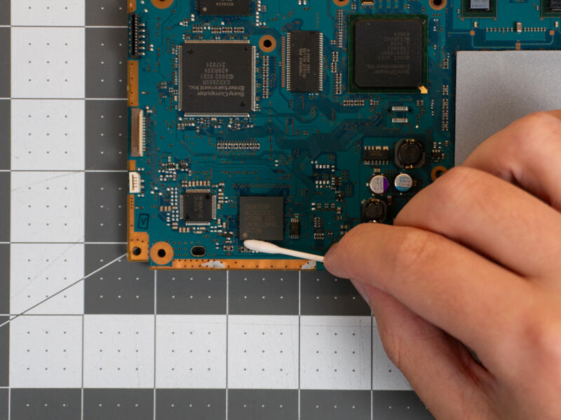
Clean the area around the IDE pads on both sides with a safe solvent like isopropyl alcohol or denatured ethanol.
Step 4.2 Test fit flex cable
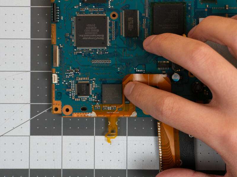
With the M.2 connector facing down like shown, align the flex cable cutout and pads with the 3 resistor arrays near the edge of the board.
Make note of where the two ground pads on the flex PCB line up with the exposed copper ground plane of the PS2.
The flex cable should lay perfectly flat against the PS2’s PCB.
Step 4.3 Prep pads
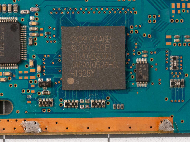
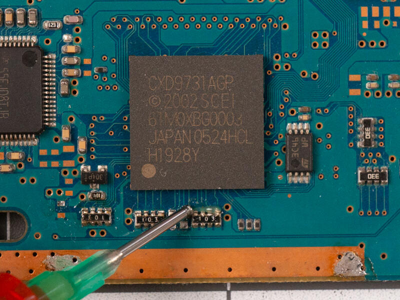
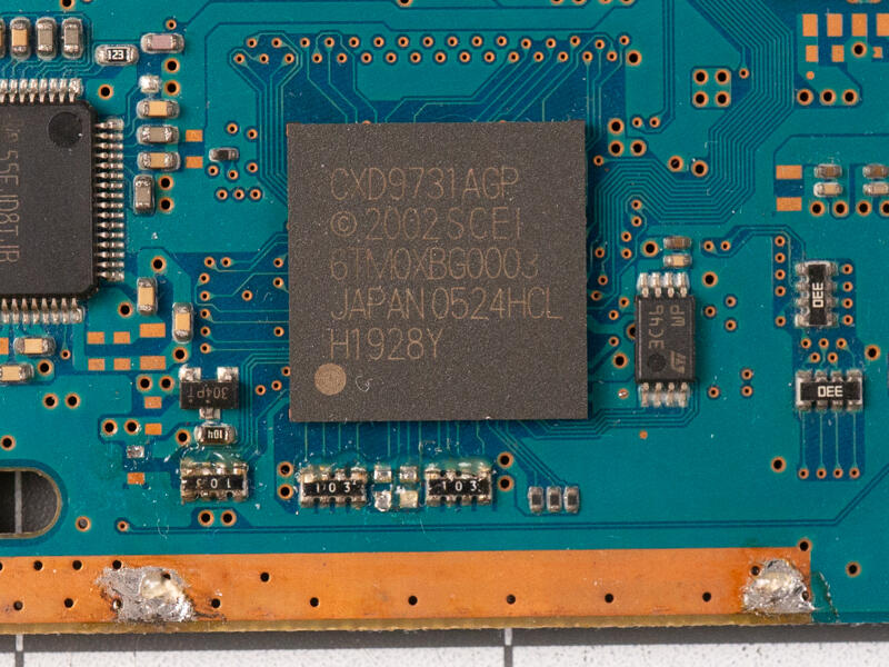
Remove the flex cable and tin the exposed copper under where the grounding pads line up with the board edge.
Apply flux to the resistor arrays and pads.
Step 4.4 Align and tac down with solder
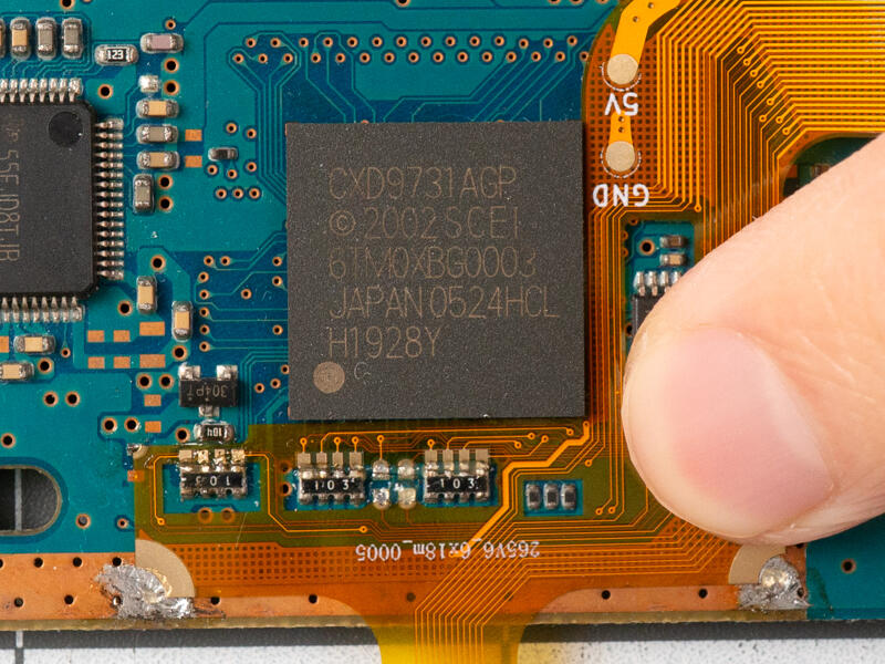
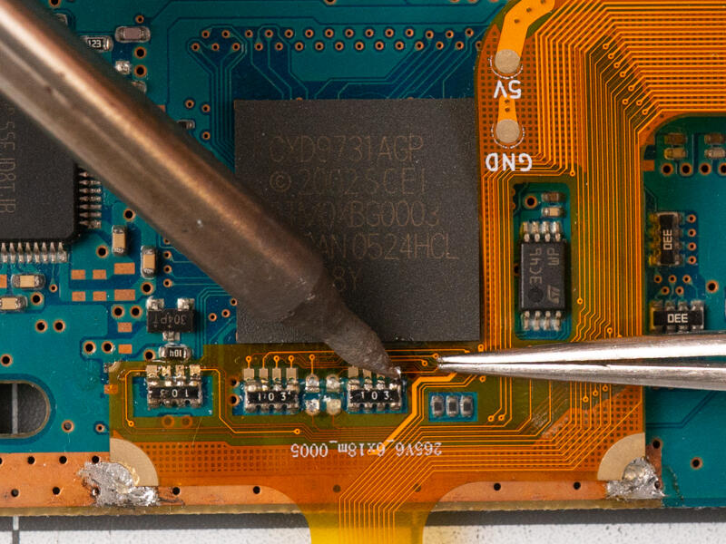
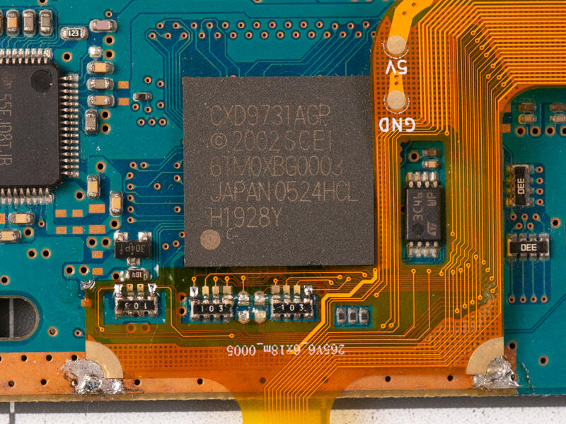
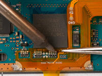
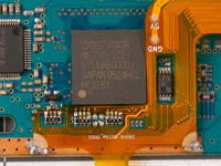
Carefully align the pads again and solder a pad at each end of the resistor arrays to tac down the flex cable.
The flex cable should lay perfectly flat against the PS2’s PCB.
Step 4.5 Continue soldering
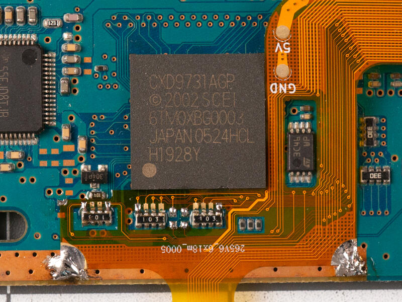
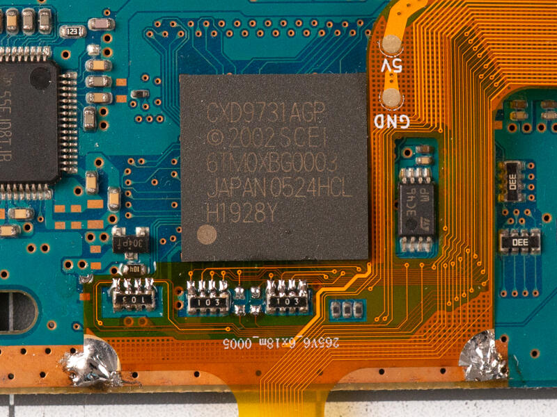
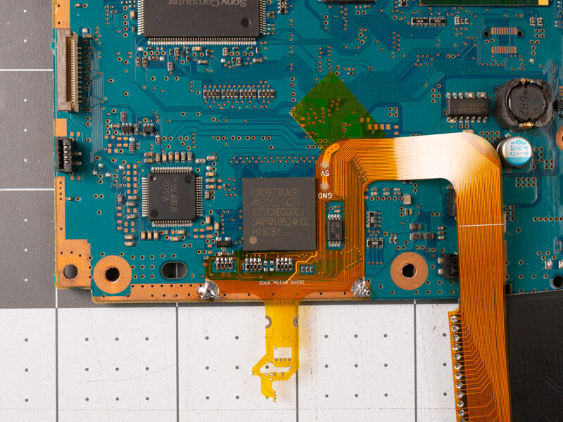
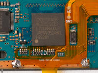
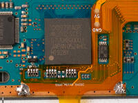
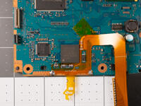
Solder down the grounding points to secure the flex PCB in place.
Solder the rest of the resistor arrays and pads.
Use some Kapton tape to secure the loose end of the flex PCB.
Step 4.6 [Will change on release version] Solder 5V
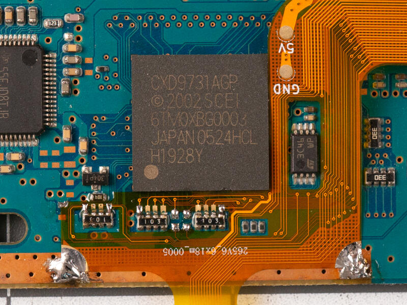
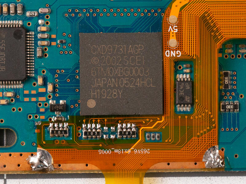
For v7 boards solder a jumper wire from the vias to the pad marked on the flex cable as shown.
Step 4.7 Flip board over
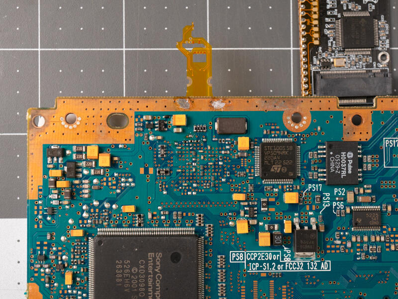
Hold the M2Slim adapter and carefully flip the board over.
Step 4.8 Prep underside pads
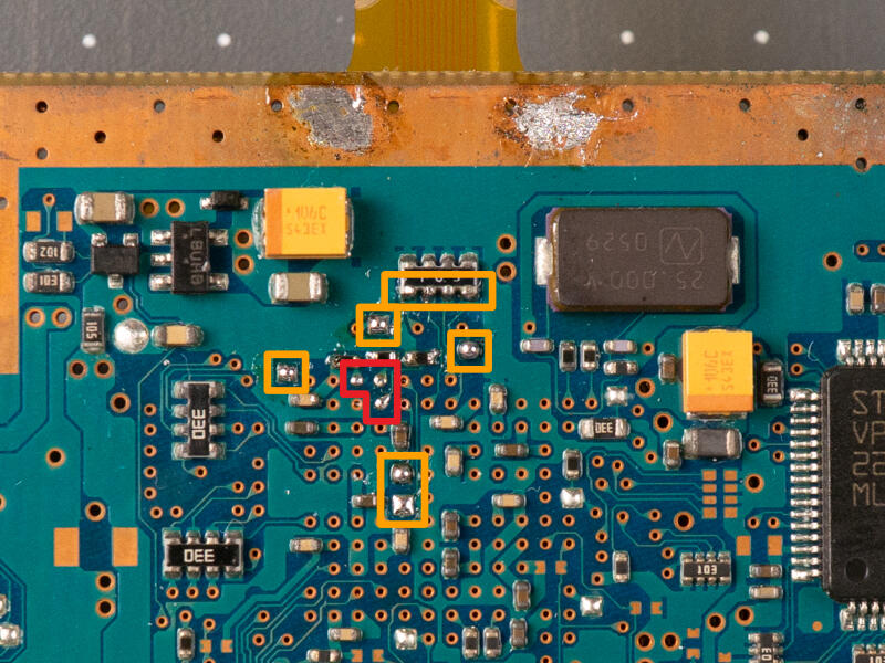
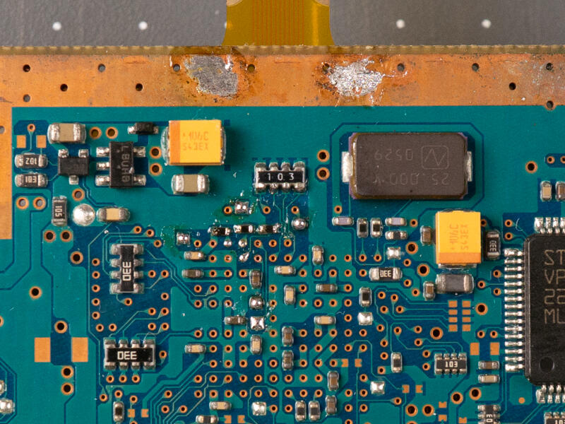
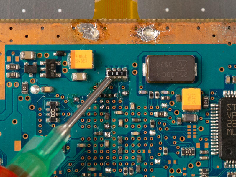
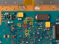
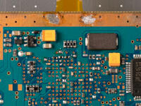
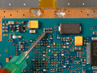
Flux and then tin the 3 vias.
Apply flux and fresh solder to the pads.
Flux is usually enough for the resistor array.
Step 4.9 Align and solder pads
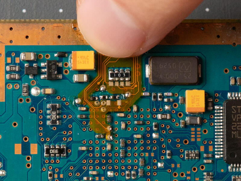
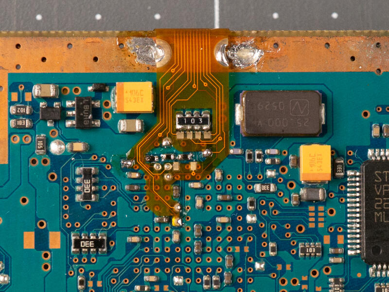
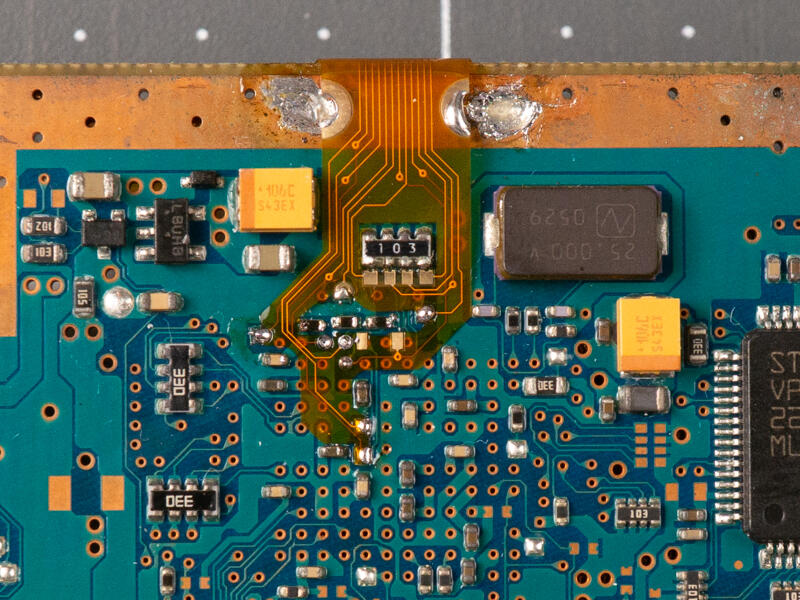
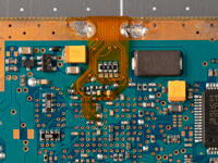
Align the 3 tinned vias with the 3 holes in the flex cable.
Tac the cable into place using some of the larger pads you tinned earlier.
Solder the vias.
You should not need to add more solder. Just touch the vias and pads with a clean iron.
Step 4.10 Finish soldering the underside
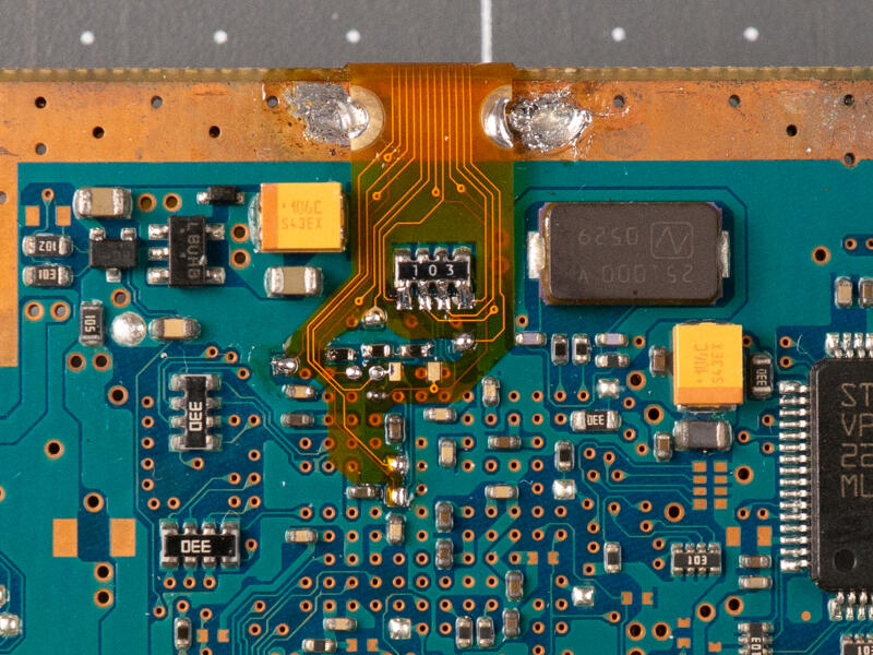
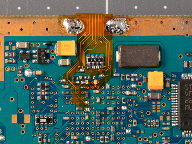
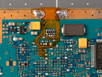
Solder the other pads and resistor array.
Solder the ground pads to provide strain relief and support.
Double check that all pads, vias and resistor array are soldered to the flex cable.